
A steam trap is an automatic valve designed to remove condensate, air, and CO2 from the steam system. The trap opens automatically to discharge condensate and closes to prevent steam loss from the system.
Over the years, a number of types of steam traps have been marketed. Although they vary in design, they all use one or more of the three basic operating principles relating to density, temperature, or velocity. Four types of steam traps have emerged which presently fill most industrial and process requirements.
STEAM TRAPS........................... (READ & DOWNLOAD)
•
Mechanical (operated by changes in fluid density).
Inverted Bucket Steam Traps


OUT SIDE VIEW INSIDE VIEW
Ball Floating Steam Trap
 Float traps are mechanical units that operate on both density and temperature principles. The float valve operates on the density principle. A level connects the ball float to the valve and seat. Once condensate reaches a certain level in the trap, the float rises, opening the orifice and draining condensate. A water seal formed by the condensate prevents live steam loss
Since the discharge valve is under water, it is not capable of venting air and non-condensables. When the accumulation of air and con-condensable gases causes a significant temperature drop, a thermostatic air vent in the top of the trap discharges them. The thermostatic vent opens at a temperature a few degrees below saturation, so it's able to handle a large volume of air-through an entirely separate orifice-but at a slightly reduced temperature.
Bimetallic Thermostatic Steam Trap
One type of thermostatic steam trap uses bimetallic elements to accuate a ball (left) or needle (right) valve assembly that discharges condensate and noncondensable gases.
 The ball valve design uses a multi-segment bimetallic element to actuate a free-floating ball valve on the downstream side of the trap. The element deflects against the line pressure with a variable increasing force in relation to rising steam pressure and temperature. The force exerted by the bimetallic element against line pressure closely parallels the steam curve, which permits the trap to operate throughout a wide pressure range without adjustment. The heart of this design is the bimetallic elements that consists of two dissimilar metals bonded together to form a composite strip. Due to the differing coefficients of expansion of the two metals, the strip will bend or deflect when subjected to a change in temperature.
 Balanced pressure thermostatic steam traps open and close via the expansion and contraction of a temperature sensitive element that responds to the lower temperatures created by condensate and noncondensable gases in the trap. The operating unit within the trap, a pressure-balanced disc or bellows, is filled with a liquid having a saturation temperature slightly below that of water. With rising temperatures in the trap, the liquid contained in the active element evaporates. The resulting internal pressure causes the bellows or disc to expand and close the valve. As condensate or air enter the trap, the temperature within the trap decreases allowing some of the liquid in the bellows to condense, which reduces the pressure inside the bellows. This reduction in pressure causes the bellows to contract. and open the valve.
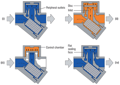
The thermodynamic trap is an extremely robust steam trap with a simple mode of operation. The trap operates by means of the dynamic effect of flash steam as it passes through the trap, as depicted in Figure 4.i. The only moving part is the disc above the flat face inside the control chamber or cap. On start-up, incoming pressure raises the disc, and cool condensate plus air is immediately discharged from the inner ring, under the disc, and out through three peripheral outlets (only 2 shown, Figure 4. ii).Hot condensate flowing through the inlet passage into the chamber under the disc drops in pressure and releases flash steam moving at high velocity. This high velocity creates a low pressure area under the disc, drawing it towards its seat (Figure 4.iii).At the same time, the flash steam pressure builds up inside the chamber above the disc, forcing it down against the incoming condensate until it seats on the inner and outer rings. At this point, the flash steam is trapped in the upper chamber, and the pressure above the disc equals the pressure being applied to the underside of the disc from the inner ring. However, the top of the disc is subject to a greater force than the underside, as it has a greater surface area.Eventually the trapped pressure in the upper chamber falls as the flash steam condenses. The disc is raised by the now higher condensate pressure and the cycle repeats (Figure 4. iv).
Over the years, a number of types of steam traps have been marketed. Although they vary in design, they all use one or more of the three basic operating principles relating to density, temperature, or velocity. Four types of steam traps have emerged which presently fill most industrial and process requirements.
STEAM TRAPS........................... (READ & DOWNLOAD)
There are three basic types of steam trap into which all variations fall
•1. Thermostatic (operated by changes in fluid temperature).
The temperature of saturated steam is determined by its pressure. In the steam space, steam gives up its enthalpy of evaporation (heat), producing condensate at steam temperature. As a result of any further heat loss, the temperature of the condensate will fall. A thermostatic trap will pass condensate when this lower temperature is sensed. As steam reaches the trap, the temperature increases and the trap closes.
•
2. Mechanical (operated by changes in fluid density).
This range of steam traps operates by sensing the difference in density between steam and condensate. These steam traps include 'ball float traps' and 'inverted bucket traps'. In the 'ball float trap', the ball rises in the presence of condensate, opening a valve, which passes the denser condensate. With the 'inverted bucket trap', the inverted bucket floats when steam reaches the trap and rises to shut the valve. Both are essentially 'mechanical' in their method of operation.
•
3. Thermodynamic (operated by changes in fluid dynamics).
Thermodynamic steam traps rely partly on the formation of flash steam from condensate. This group includes 'thermodynamic', 'disc', 'impulse' and 'labyrinth' steam traps.
3. Thermodynamic (operated by changes in fluid dynamics).
Thermodynamic steam traps rely partly on the formation of flash steam from condensate. This group includes 'thermodynamic', 'disc', 'impulse' and 'labyrinth' steam traps.
Mechanical (operated by changes in fluid density).
Inverted Bucket Steam Traps

OUT SIDE VIEW INSIDE VIEW
Inverted bucket steam traps are the most robust type of mechanical trap and resist water hammer. The design works on the principle of differentiating between the density of steam and water condensate. Steam entering under the submerged, inverted bucket causes it to float, which closes the discharge valve located at the top of the trap. Condensate entering the trap causes the bucket to sink, opening the valve to remove condensate. Normally there is a small vent in the top of the bucket, which allows non-condensable gases to pass through for discharge with the condensate. Inverted bucket steam traps are often found on higher-pressure steam systems, but they have also found use in lower-pressure service, where one might normally find float and thermostatic traps, because of their low maintenance and long lasting characteristics. With the addition of a check valve at the trap inlet, the inverted bucket can also be used to remove condensate from superheated steam lines. They must be installed in a vertical position and are used for a wide variety of service applications.
Ball Floating Steam Trap
 Float traps are mechanical units that operate on both density and temperature principles. The float valve operates on the density principle. A level connects the ball float to the valve and seat. Once condensate reaches a certain level in the trap, the float rises, opening the orifice and draining condensate. A water seal formed by the condensate prevents live steam loss
Since the discharge valve is under water, it is not capable of venting air and non-condensables. When the accumulation of air and con-condensable gases causes a significant temperature drop, a thermostatic air vent in the top of the trap discharges them. The thermostatic vent opens at a temperature a few degrees below saturation, so it's able to handle a large volume of air-through an entirely separate orifice-but at a slightly reduced temperature.
Thermostatic Steam Traps
 Thermostatic steam traps open and close with the movement of a temperature sensitive element. As steam condenses, the newly formed condensate is at steam temperature, but as it flows to the steam trap, it cools. When the temperature inside
 the steam trap has dropped to a specified value below the steam temperature, the thermostatic valve will open, and line pressure will force condensate and noncondensable gases out of the trap. Once entering steam reheats the trap to the desired temperature, the thermostatic valve will close preventing the discharge of live steam.
 Thermostatic steam traps open and close with the movement of a temperature sensitive element. As steam condenses, the newly formed condensate is at steam temperature, but as it flows to the steam trap, it cools. When the temperature inside
 There are two basic designs for a thermostatic steam trap, a bimetallic and a balanced pressure design. Both use the difference in temperature between live steam and condensate or air to control the release of water and noncondensable gases from the steam line.
Bimetallic Thermostatic Steam Trap
One type of thermostatic steam trap uses bimetallic elements to accuate a ball (left) or needle (right) valve assembly that discharges condensate and noncondensable gases.
 The ball valve design uses a multi-segment bimetallic element to actuate a free-floating ball valve on the downstream side of the trap. The element deflects against the line pressure with a variable increasing force in relation to rising steam pressure and temperature. The force exerted by the bimetallic element against line pressure closely parallels the steam curve, which permits the trap to operate throughout a wide pressure range without adjustment. The heart of this design is the bimetallic elements that consists of two dissimilar metals bonded together to form a composite strip. Due to the differing coefficients of expansion of the two metals, the strip will bend or deflect when subjected to a change in temperature.
Most designs have the ball valve wide open when the trap is cold. This allows air and condensate to discharge rapidly during initial pressurization of the steam line. As warmer condensate enters the trap, the bimetallic element deflects slowly to close the valve. By the time live steam reaches the trap, the element has deflected so as to completly close the ball valve on the exit side of the trap.
When condensate or air enters the trap, their temperature is below that of saturated steam and the consequent reaction of the element is insufficient to keep the valve tightly closed allowing line pressure on the valve to overcome the pull of the element and open the valve. When live steam again enters the trap, the element deflects to once again tightly close the exit side ball valve preventing the loss of live steam.
Balanced Pressure Thermostatic Steam Trap
 Balanced pressure thermostatic steam traps open and close via the expansion and contraction of a temperature sensitive element that responds to the lower temperatures created by condensate and noncondensable gases in the trap. The operating unit within the trap, a pressure-balanced disc or bellows, is filled with a liquid having a saturation temperature slightly below that of water. With rising temperatures in the trap, the liquid contained in the active element evaporates. The resulting internal pressure causes the bellows or disc to expand and close the valve. As condensate or air enter the trap, the temperature within the trap decreases allowing some of the liquid in the bellows to condense, which reduces the pressure inside the bellows. This reduction in pressure causes the bellows to contract. and open the valve.
 Thermodynamic or Disk Steam Traps
 |
Thermodynamic steam traps are preferably installed with the controlling disc in a horizontal position. The traps are used in applications where there will be no adverse effects from a temporary accumulation of condensate due to the intermittent operation of the trap. These applications include: pressing units, drying units, and steam jacket pipelines.


0 comments:
Post a Comment