Injector

For other uses, see Injector (disambiguation) and Ejector (disambiguation).

Diagram of a typical modern ejector.
An injector, ejector, steam ejector, steam injector,eductor-jet pump or thermocompressor is a type o fpump that uses the Venturi effect of a converging-diverging nozzle to convert the pressure energy of a motive fluid to velocity energy which creates a low pressure zone that draws in and entrains a suction fluid. After passing through the throat of the injector, the mixed fluid expands and the velocity is reduced which results in recompressing the mixed fluids by converting velocity energy back into pressure energy. The motive fluid may be a liquid, steam or any other gas. The entrained suction fluid may be a gas, a liquid, a slurry, or a dust-laden gas stream.
The adjacent diagram depicts a typical modern ejector. It consists of a motive fluid inlet nozzle and a converging-diverging outlet nozzle. Water, air, steam, or any other fluid at high pressure provides the motive force at the inlet.

The Venturi effect, a particular case of Bernoulli's principle, applies to the operation of this device. Fluid under high pressure is converted into a high-velocity jet at the throat of the convergent-divergent nozzle which creates a low pressure at that point. The low pressure draws the suction fluid into the convergent-divergent nozzle where it mixes with the motive fluid.

In essence, the pressure energy of the inlet motive fluid is converted to kinetic energy in the form of velocity head at the throat of the convergent-divergent nozzle. As the mixed fluid then expands in the divergent diffuser, the kinetic energy is converted back to pressure energy at the diffuser outlet in accordance with Bernoulli's principle. There are very few steam locomotives still in operation today other than as tourist attractions. However, when steam locomotives were in use many years ago, injectors were used to pump water into the locomotive's steam-producing boiler and some of the steam was used as the injector's motive fluid. Such "steam injectors" took advantage of the latent heat released by the resulting condensation of the motive steam.

Depending on the specific application, an injector takes the form of an eductor-jet pump, a water eductor, a vacuum ejector, asteam-jet ejector, or an aspirator.

Key design parameters
The compression ratio of the injector, , is defined as ratio of the injectors's outlet pressure to the inlet pressure of the suction fluid .
The entrainment ratio of the injector, , is defined as the amount of motive fluid (in kg/hr) required to entrain and compress a given amount (in kg/hr) of suction fluid..

The compression ratio and the entrainment ratio are key parameters in designing an injector or ejector.

History

A- Steam from boiler, B- Needle valve, C- Needle valve handle, D- Steam and water combine, E- Water feed, F- Combining cone, G- Delivery nozzle and cone, H- delivery chamber and pipe, K- Check valve, L- Overflow

A more modern drawing of the injector used in steam locomotives.

Steam injector of a steam locomotive boiler.

The injector was invented by a Frenchman, Henri Giffard in 1858and patented in the United Kingdomby Messrs Sharp Stewart & Co. of Glasgow. Motive force was provided at the inlet by a suitable high-pressure fluid.
Feedwater injectors
The injector was originally used in the boilers of steam locomotives for injecting or pumping the boiler feedwater into the boiler. The injector consisted of a body containing a series of three or more nozzles, "cones" or "tubes". The motive steam passed through a nozzle that reduced its pressure below atmospheric and increased the steam velocity. Fresh water was entrained by the steam jet, and both steam and water entered a convergent "combining cone" which mixed them thoroughly so that the water condensed the steam. The condensate mixture then entered a divergent "delivery cone" which slowed down the jet, and thus built up the pressure to above that of the boiler. An overflow was required for excess steam or water to discharge, especially during starting. There was at least one check valve between the exit of the injector and the boiler to prevent back flow, and usually a valve to prevent air being sucked in at the overflow.

After some initial scepticism resulting from the unfamiliar and superficially paradoxical mode of operation, the injector was widely adopted as an alternative to mechanical pumps in steam-driven locomotives. The key to understanding how it works is to appreciate that steam, having a much lower density than water, attains a much higher velocity than water would do in flowing from a high pressure to a low pressure through the steam cone. When this jet of steam meets cold water in the combining cone, the principle of conservation of momentum applies. The steam is condensed by mixing with the cold water but the flow of water is accelerated by absorbing the momentum of the high velocity water molecules condensed from the steam. Since the steam, in condensing, gives up its latent heat energy, this causes the temperature of the resultant jet of water to be raised. When this accelerated jet of water passes through the delivery cone, it is capable to developing a much higher pressure than that of the original supply of steam and is thus able to overcome the boiler pressure at the check valve, thereby allowing water to enter the boiler. Furthermore, the addition of heat to the flow of water lessens the effect of the injected water in cooling the water in the boiler compared to the case of cold water injected via a mechanical feed pump. Most of the heat energy in the condensed steam is therefore returned to the boiler, increasing the thermal efficiency of the process. Injectors were therefore simple and reliable and also thermally efficient.

Efficiency was further improved by the development of a multi-stage injector which was powered not by live steam from the boiler but by exhaust steam from the cylinders, thereby making use of the residual energy in the exhaust steam which would otherwise have gone to waste.

Injectors could be troublesome under certain running conditions, when vibration caused the combined steam and water jet to "knock off". Originally the injector had to be restarted by careful manipulation of the steam and water controls, and the distraction caused by a malfunctioning injector was largely responsible for the 1913 Ais Gill rail accident. Later injectors were designed to automatically restart on sensing the collapse in vacuum from the steam jet, for example with a spring-loaded delivery cone.
Vacuum ejectors
An additional use for the injector technology was in vacuum ejectors in continuous train braking systems, which were made compulsory in the UK by the Regulation of Railways Act 1889. A vacuum ejector uses steam pressure to draw air out of the vacuum pipe and reservoirs of continuous train brake. Steam locomotives, with a ready source of steam, found ejector technology ideal with its rugged simplicity and lack of moving parts. Vacuum brakes have been superseded by air brakes in modern trains, which use pumps, as diesel and electric locomotives no longer have a suitable working fluid for vacuum ejectors.
Modern uses
The use of injectors (or ejectors) in various industrial applications has become quite common due to their relative simplicity and adaptability. For example:
To inject chemicals into the boiler drums of small, stationary, low pressure boilers. In large, high-pressure modern boilers, usage of injectors for chemical dosing is not possible due to their limited outlet pressures.
In thermal power stations, they are used for the removal of the boiler bottom ash, the removal of fly ash from the hoppers of theelectrostatic precipitators used to remove that ash from the boiler flue gas, and for creating a vacuum pressure in steam turbine exhaust condensers.
Jet pumps have been used in boiling water nuclear reactors to circulate the coolant fluid.
For use in producing a vacuum pressure in steam jet cooling systems.
For the bulk handling of grains or other granular or powdered materials.
The construction industry uses them for pumping turbid water and slurries.
Some aircraft (mostly earlier designs) use an ejector attached to the fuselage to provide vacuum for gyroscopic instruments such as an attitude indicator.
aspirators are vacuum pumps based on the same operating principle and are used in laboratories to create a partial vacuum and for medical use in suction of mucus or bodily fluids.
Water eductors are water pumps used for dredging silt and panning for gold, they're used because they can handle quite well the highly abrasive mixtures that are pumped

Condensate Recover

Condensate Return Systems provide excellent opportunities for substantial savings in energy, water and chemical costs.
Improvements to a condensate return system often are also beneficial from the perspective of production efficiencies.
The cost saving due to returning the water content of condensate to the boiler as feedwater requires no great cost benefit analysis. The unit costs of boiler water, treatment chemicals and effluent charges are usually well known in a plant, as is the energy cost to provide both sensible and latent heat to the feedwater in the boiler.
Usually less well documented is the loss due to flash steam, occuring as a result of condensate pressure drop.

Primary pressure drop in steam condensate systems is usually across the steam trap of a particular heat exchanger or other steam-heated equipment.

Take the example of a typical Cardboard Corrugator, and assume a supply pressure to the steam-heated rolls of 10 bar g and a condensate return line pressure of 0.5 bar g. The resulting flash steam percentage can be read off the graph as about 14%. Assuming a steam usage for this particular steam-heated roll of 100 kg/h, the flash steam would amount to 14 kg/h.

If a dual-pressure steam system is used, with the hot plate section supplied with 3 - 4 bar g steam, the amount of flash steam from this roll would be about halved to 7 - 8% or 7 - 8 kg/h.

Basic Options for Flash Steam Utilisation:

1. Reduce amount of flash steam by reducing the steam pressure in a process. This also has the added benefit of increased latent heat value corresponding to lower steam pressures, resulting in extra steam cost savings.

2. Install a Flash Vessel and use the flash steam for pre-heating a process medium using lower pressure steam. Paper machines and Corrugators are obvious candidates, as are many processes in the petrochemical and food industries. Pre-heating of boiler feedwater and combustion air are almost always available as possible heat sinks.

3. Use high pressure condensate return to reduce the amount of flash steam formation. This can result in dramatic energy savings in systems where a minimum pressure differential exists at all times. Usually this applies to systems where the steam pressure remains essentially constant. Condensate can then be collected in a pressure vessel and pumped directly back to the boiler.

Alternatively,where the steam supply pressure modulates (for instance by means of temperature or pressure regulating valves), a deaerator can be a useful "condensate pressure controller".

In a deaerator, flash steam directly replaces live steam usage for removal of O2 and CO2 from boiler feedwater.

Our standard deaerators normally operate at 0.5 to 1 bar g, in order to achieve the minimum temperature needed for proper deaeration. However, they can be purpose built for any higher pressure if this is cost-efficient from the aspect of maximum flash steam utilisation.

Another benefit of pressurised condensate returns, especially when a deaerator is employed, is the utilisation of the inevitable live steam losses through steam traps and other equipment.
SYSTEM DESCRIPTION
A boiler supplies 10 bar g steam to a Corrugator.

The boiler plant incorporates a Flue Gas Heat Recovery System A, as well as a Continuous Blowdown Heat Recovery System B, both of which serve to pre-heat cold make-up water.

The deaerator operates with 0.5 bar g steam supply. Its primary function is the mechanical deaeration of feed water to minimise the cost of oxygen scavenging chemicals. The deaerator also serves as an important recipient of pressurised condensate and flash steam, as well as live steam losses from steam traps. This secondary function alone can often justify the cost of a deaerator.

A Steam Dryer is installed in the 10 bar g steam main close to the boiler, to ensure highest heat transfer efficiency for the process.

The corrugator rolls are fed with 10 bar steam, depicted as SectionC. Steam pressure to the rolls is essentially constant.

A Pressure Reducing Valve drops 10 bar g steam to 4 bar g for the Hot Plate Section D.

Condensate from the Rolls Section C is expanded in a Flash Vessel. Flash steam is piped into the 4 bar g Section D steam supply, where it replaces an equivalent amount of live steam. For this example, about 7% of condensate flashes from 10 bar g to 4 bar g.
Remaining condensate from Section C flows by differential pressure to the deaerator.

The Hot Plate Section D is equipped with individual pressure controls for temperature adjustment. Therefore the pressure differential may at times be insufficient to transport condensate from Section D back to the deaerator.
A Thermgard LIFTMASTER condensate pump is employed to ensure automatic condensate removal from the Hot Plate Section D back to the deaerator. The pump is steam-activated on demand, and requires no electrical power or control. Steam consumption is about 1 kg per 1000 kg condensate pumped.

ADVANTAGES OF CLOSED LOOP CONDENSATE RETURN:
Minimal make-up water requirement = substantial water and treatment chemical cost savings.

Oxygen-scavenging chemical costs drastically reduced.

Greatly reduced blowdown requirements = lower water, chemical and energy costs.

Boiler fuel cost savings 10 - 15 % due to utilisation of flash steam.

Water and fuel cost savings due to utilisation of live steam losses from steam traps etc

Flash vessel

BOILER BLOWDOWN is necessary for two separate and distinct reasons:
1. To ensure that the concentration of total dissolved solids (TDS) is kept below a certain maximum allowable level.
2. To prevent the accumulation of suspended solids that collect at the bottom of the boiler drum.

BOILER BLOWDOWN should consequently be carried out in two distinct steps:
1. Continuous blowdown from just below the low water level for the purpose of control of Total Dissolved Solids of boiler water.
Continuous blowdown lends itself ideally to recovery of some 80% of heat content and 10 - 20% (depending on boiler pressure) of pure water in the form of condensed flash steam.


2. Bottom blowdown to remove suspended solids should be carried out on an intermittent basis from the bottom of the boiler drum. Specialised valves are available to handle this arduous duty of handling hot boiler water containing solid particles, with reliable shut-off for long periods. The intermittent blowdown can be automated via programmable cycle timers. Discharge of bottom blowdown is to a blowdown vessel at atmospheric pressure. A cooling system may be required to ensure that blowdown temperature going to sewer is within stipulated limits. An exhaust head and silencer may also be necessary to avoid nuisance water and noise emissions from the vent stack of the blowdown vessel

Blowdown vessels are a preferred alternative to blowdown pits. The following information is extracted from HSE Guidance Note PM60 and provides information that may be useful in places other than the UK:
Traditionally, blowdown vessels have had tangential inlets. However, this has meant that the vessels have been structurally weak at the point where the inlet enters.
A preferred alternative is to bring the blowdown line in radially, giving a structurally superior vessel, and then fitting a diffuser inside the vessel. This arrangement also reduces the erosion which could occur inside a vessel with a tangential inlet.


Construction standard
The vessel will need to conform to the European Pressure Equipment Directive (2002) for Group 2 gases. This directive instructs the manufacturer to conform to design and manufacturing standards. As this is a pressure vessel specification, the vessel also needs provision for inspection including an access door and a drain.
Design temperature and pressure
The blowdown vessel design pressure should be at least 25% of the boiler maximum working pressure and the design temperature should be greater than or equal to the saturation temperature for the vessel design pressure.

Fig. 3.14.4
A blowdown vessel installation on a single boiler

Size
This depends on the boiler pressure and blowdown line size, however:
The vent should be large enough, that pressure within the vessel does not exceed 0.35 bar g.
The volume of standing water must ensure that the overflowing water temperature does not exceed 43°C.

Operation
The vessel should operate with a quantity of standing water, and the water quantity should be at least twice the quantity of blowdown water. Approximately half of the tank's volume should be occupied by standing water and the remainder as air space.

Vent
The vent should ensure that flash steam is vented safely and there is no significant carryover of water at the exit to the vent pipe. The vent should be as straight as possible and ideally terminated with a vent head.
Tapping for a pressure gauge

The vessel must have a tapping for a pressure gauge, as the vessel is manufactured to a pressure vessel specification and regular testing and inspection are required.
Cooling system

A cooling device should be fitted to the vessel if the hot water temperature causes the outlet temperature at blowdown to exceed the permissible limit. The most cost-effective choice for this application is a self-acting control valve. If the temperature exceeds the set temperature, the valve will open and allow cold mains water into the vessel.

Multi-boiler installations
The piping arrangement for multi-boiler installations is covered in the UK HSE Guidance Note (PM60); the following points are made:
Operation
Only one boiler can be blown down at any one time. In fact, sizing of the blowdown vessel will be based on the highest pressure boiler with the biggest blowdown line size. Reference is also made to the UK Factories Act (1961) which states the same thing.
Piping

Figure 3.14.5 shows the recommended layout for multiple boiler installations where the bottom and TDS blowdown lines are taken back separately to the blowdown vessel. Manifolding should be at the vessel and not at the boiler. Separate connections are required on the vessel for bottom blowdown and for TDS blowdown return lines.

A third connection is also needed on the vessel to comply with UK Guidance Notes (BG01 and INDG436) regarding water level control in boilers. This requires a connection for the blowdown from control chambers and level gauge glasses.


Valving
Where blowdown lines connect into an inlet manifold on the vessel, each must be fitted with either a screw down non-return valve or, a non-return valve and an isolating valve. This is to prevent the possibility of steam and pressurised hot water being blown from one working boiler into another (inside which personnel may be working) during maintenance.


The preference is for two separate valves. The check valve will have to work regularly, hence wear on the seat is inevitable.


Fig. 3.14.5
A blowdown vessel
on a multi-boiler installation

gauges glass

All boilers must be fitted with at least one pressure indicator.
The usual type is a simple pressure gauge constructed to EN 12953.
The dial should be at least 150 mm in diameter and of the Bourdon tube type, it should be marked to indicate the normal working pressure and the maximum permissible working pressure / design pressure.
Pressure gauges are connected to the steam space of the boiler and usually have a ring type siphon tube which fills with condensed steam and protects the dial mechanism from high temperatures.

Pressure gauges may be fitted to other pressure containers such as blowdown vessels, and will usually have smaller dials as shown in Figure 3.7.9.


Typical pressure gauge with ring siphon

Gauge glasses and fittings

All steam boilers are fitted with at least one water level indicator, but those with a rating of 100 kW or more should be fitted with two indicators. The indicators are usually referred to as gauge glasses complying with EN 12953.
Fig. 3.7.10
Gauge glass and fittings

A gauge glass shows the current level of water in the boiler, regardless of the boiler's operating conditions. Gauge glasses should be installed so that their lowest reading will show the water level at 50 mm above the point where overheating will occur. They should also be fitted with a protector around them, but this should not hinder visibility of the water level. Figure 3.7.10 shows a typical gauge glass.

Gauge glasses are prone to damage from a number of sources, such as corrosion from the chemicals in boiler water, and erosion during blowdown, particularly at the steam end. Any sign of corrosion or erosion indicates that a new glass is required.

When testing the gauge glass steam connection, the water cock should be closed. When testing the gauge glass water connections, the steam cock pipe should be closed.

To test a gauge glass, the following procedure should be followed:
Close the water cock and open the drain cock for approximately 5 seconds.
Close the drain cock and open the water cock.

Water should return to its normal working level relatively quickly. If this does not happen, then a blockage in the water cock could be the reason, and remedial action should be taken as soon as possible.
Close the steam cock and open the drain cock for approximately 5 seconds.
Close the drain cock and open the steam cock.

If the water does not return to its normal working level relatively quickly, a blockage may exist in the steam cock. Remedial action should be taken as soon as possible.

The authorised attendant should systematically test the water gauges at least once each day and should be provided with suitable protection for the face and hands, as a safeguard against scalding in the event of glass breakage.

Note: that all handles for the gauge glass cocks should point downwards when in the running condition.
Gauge glass guards

The gauge glass guard should be kept clean. When the guard is being cleaned in place, or removed for cleaning, the gauge should be temporarily shut-off.

Make sure there is a satisfactory water level before shutting off the gauge and take care not to touch or knock the gauge glass. After cleaning, and when the guard has been replaced, the gauge should be tested and the cocks set in the correct position.


Maintenance
The gauge glass should be thoroughly overhauled at each annual survey. Lack of maintenance can result in hardening of packing and seizure of cocks. If a cock handle becomes bent or distorted special care is necessary to ensure that the cock is set full open. A damaged fitting should be renewed or repaired immediately. Gauge glasses often become discoloured due to water conditions; they also become thin and worn due to erosion. Glasses, therefore, should be renewed at regular intervals.

A stock of spare glasses and cone packing should always be available in the boiler house. Remember:
If steam passes are choked a false high water level may be given in the gauge glass. After the gauge has been tested a false high water level may still be indicated.
If the water passages are choked an artificially high water level may be observed due to steam condensing in the glass. After testing, the glass will tend to remain empty unless the water level in the boiler is higher than the top connection, in which case water might flow into the glass from this connection.
Gauge glass levels must be treated with the utmost respect, as they are the only visual indicator of water level conditions inside the boiler. Any water level perceived as abnormal must be investigated as soon as it is observed, with immediate action taken to shut down the boiler burner if necessary.

All boilers must be fitted with at least one pressure indicator.
The usual type is a simple pressure gauge constructed to EN 12953.
The dial should be at least 150 mm in diameter and of the Bourdon tube type, it should be marked to indicate the normal working pressure and the maximum permissible working pressure / design pressure.
Pressure gauges are connected to the steam space of the boiler and usually have a ring type siphon tube which fills with condensed steam and protects the dial mechanism from high temperatures.

Pressure gauges may be fitted to other pressure containers such as blowdown vessels, and will usually have smaller dials as shown in Figure 3.7.9.
Fig. 3.7.9
Typical pressure gauge with ring siphon

Gauge glasses and fittings

All steam boilers are fitted with at least one water level indicator, but those with a rating of 100 kW or more should be fitted with two indicators. The indicators are usually referred to as gauge glasses complying with EN 12953.
Fig. 3.7.10
Gauge glass and fittings

A gauge glass shows the current level of water in the boiler, regardless of the boiler's operating conditions. Gauge glasses should be installed so that their lowest reading will show the water level at 50 mm above the point where overheating will occur. They should also be fitted with a protector around them, but this should not hinder visibility of the water level. Figure 3.7.10 shows a typical gauge glass.

Gauge glasses are prone to damage from a number of sources, such as corrosion from the chemicals in boiler water, and erosion during blowdown, particularly at the steam end. Any sign of corrosion or erosion indicates that a new glass is required.

When testing the gauge glass steam connection, the water cock should be closed. When testing the gauge glass water connections, the steam cock pipe should be closed.

To test a gauge glass, the following procedure should be followed:
Close the water cock and open the drain cock for approximately 5 seconds.
Close the drain cock and open the water cock.

Water should return to its normal working level relatively quickly. If this does not happen, then a blockage in the water cock could be the reason, and remedial action should be taken as soon as possible.
Close the steam cock and open the drain cock for approximately 5 seconds.
Close the drain cock and open the steam cock.

If the water does not return to its normal working level relatively quickly, a blockage may exist in the steam cock. Remedial action should be taken as soon as possible.

The authorised attendant should systematically test the water gauges at least once each day and should be provided with suitable protection for the face and hands, as a safeguard against scalding in the event of glass breakage.

Note: that all handles for the gauge glass cocks should point downwards when in the running condition.
Gauge glass guards

The gauge glass guard should be kept clean. When the guard is being cleaned in place, or removed for cleaning, the gauge should be temporarily shut-off.

Make sure there is a satisfactory water level before shutting off the gauge and take care not to touch or knock the gauge glass. After cleaning, and when the guard has been replaced, the gauge should be tested and the cocks set in the correct position.

Maintenance
The gauge glass should be thoroughly overhauled at each annual survey. Lack of maintenance can result in hardening of packing and seizure of cocks. If a cock handle becomes bent or distorted special care is necessary to ensure that the cock is set full open. A damaged fitting should be renewed or repaired immediately. Gauge glasses often become discoloured due to water conditions; they also become thin and worn due to erosion. Glasses, therefore, should be renewed at regular intervals.

A stock of spare glasses and cone packing should always be available in the boiler house. Remember:
If steam passes are choked a false high water level may be given in the gauge glass. After the gauge has been tested a false high water level may still be indicated.
If the water passages are choked an artificially high water level may be observed due to steam condensing in the glass. After testing, the glass will tend to remain empty unless the water level in the boiler is higher than the top connection, in which case water might flow into the glass from this connection.
Gauge glass levels must be treated with the utmost respect, as they are the only visual indicator of water level conditions inside the boiler. Any water level perceived as abnormal must be investigated as soon as it is observed, with immediate action taken to shut down the boiler burner if necessary.

Air vents and vacuum breakers

When a boiler is started from cold, the steam space is full of air. This air has no heat value, and will adversely affect steam plant performance due to its effect of blanketing heat exchange surfaces. The air can also give rise to corrosion in the condensate system, if not removed adequately.
The air may be purged from the steam space using a simple cock; normally this would be left open until a pressure of about 0.5 bar is showing on the pressure gauge. An alternative to the cock is a balanced pressure air vent which not only relieves the boiler operator of the task of manually purging air (and hence ensures that it is actually done), it is also much more accurate and will vent gases which may accumulate in the boiler. Typical air vents are shown in Figure 3.7.14.
When a boiler is taken off-line, the steam in the steam space condenses and leaves a vacuum. This vacuum causes pressure to be exerted on the boiler from the outside, and can result in boiler inspection doors leaking, damage to the boiler flat plates and the danger of overfilling a shutdown boiler. To avoid this, a vacuum breaker (see Figure 3.7.14) is required on the boiler shell.

Level control chambers


Fig. 3.7.11 - External level control chamber
Level control chambers are fitted externally to boilers for the installation of level controls or alarms, as shown in Figure 3.7.11.

The function of the level controls or alarms is checked daily using the sequencing purge valves. With the handwheel turned fully anticlockwise the valve is in the 'normal working' position and a back seating shuts off the drain connection. The handwheel dial may look similar to that shown in Figure 3.7.12. Some handwheels have no dial, but rely on a mechanism for correct operation.

The following is a typical procedure that may be used to test the controls when the boiler is under pressure, and the burner is firing:
  • Slowly turn the handwheel clockwise until the indicating pointer is at the first 'pause' position. The float chamber connection is baffled, the drain connection is opened, and the water connection is blown through.
  • Pause for 5 to 8 seconds.
  • Slowly move the handwheel further clockwise to full travel. The water connection is shut-off, the drain valve remains open, and the float chamber and steam connections are blown through. The boiler controls should operate as for lowered water level in boiler i.e. pump running and / or audible alarm sounding and burner cut-out. Alternatively if the level control chamber is fitted with a second or extra low water alarm, the boiler should lock-out.
  • Pause for 5 to 8 seconds.
  • Slowly turn the handwheel fully anticlockwise to shut-off against the back seating in the 'normal working' position.
Sequencing purge valves are provided by a number of different manufacturers. Each may differ in operating procedure. It is essential that the manufacturer's instructions be followed regarding this operation

Boiler stop valves


Fig. 3.7.3
Boiler stop valve

A steam boiler must be fitted with a stop valve (also known as a crown valve) which isolates the steam boiler and its pressure from the process or plant. It is generally an angle pattern globe valve of the screw-down variety. Figure 3.7.3 shows a typical stop valve of this type.

In the past, these valves have often been manufactured from cast iron, with steel and bronze being used for higher pressure applications. In the UK, BS 2790 (eventually to be replaced with EN 12953) states that cast iron valves are no longer permitted for this application on steam boilers. Nodular or spheroidal graphite (SG) iron should not be confused with grey cast iron as it has mechanical properties approaching those of steel. For this reason many boilermakers use SG iron valves as standard.

The stop valve is not designed as a throttling valve, and should be fully open or closed. It should always be opened slowly to prevent any sudden rise in downstream pressure and associated waterhammer, and to help restrict the fall in boiler pressure and any possible associated priming.

To comply with UK regulations, the valve should be of the 'rising handwheel' type. This allows the boiler operator to easily see the valve position, even from floor level. The valve shown is fitted with an indicator that makes this even easier for the operator.

On multi-boiler applications an additional isolating valve should be fitted, in series with the crown valve. At least one of these valves should be lockable in the closed position. The additional valve is generally a globe valve of the screw-down, non-return type which prevents one boiler pressurising another. Alternatively, it is possible to use a screw-down valve, with a disc check valve sandwiched between the flanges of the crown valve and itself.

Feedwater check valves

The feedwater check valve (as shown in Figures 3.7.4 and 3.7.5) is installed in the boiler feedwater line between the feedpump and boiler. A boiler feed stop valve is fitted at the boiler shell.
The check valve includes a spring equivalent to the head of water in the elevated feedtank when there is no pressure in the boiler. This prevents the boiler being flooded by the static head from the boiler feedtank.
Fig. 3.7.4
Boiler check valve
Under normal steaming conditions the check valve operates in a conventional manner to stop return flow from the boiler entering the feedline when the feedpump is not running. When the feedpump is running, its pressure overcomes the spring to feed the boiler as normal.
Because a good seal is required, and the temperatures involved are relatively low (usually less than 100°C) a check valve with a EPDM (Ethylene Propylene) soft seat is generally the best option.
  
Location of feed check valve

Have a look!!!!!!!!!!!

I.D & FD Fans

HUMIAIR fans are of sheet steel construction with backward curved self cleaning blades. The self – cleaning efficiency of an induced draft fan will increase when the tip angle of the blade is enlarged.
These fans are, therefore, suitable for:-

Kitchen Exhaust
Dust Collector System
Fume Exhaust
Welding Shops
Pharmaceuticals
Chemicals
Engineering Industry
Automobiles

Induced Draft
Type Total Pressure mm WG
AMRL 300
AMRM 600
AHRM 900
These fans are available for air quantity from 500 CMH to 10,000 CMH.

Fans that are used to evacuate a space or create negative air pressure in a system are referred to as induced draft fans. Occasionally, manufacturing spaces are required by specifications to be maintained at a specific negative pressure. Induced draft is also used to identify the combustion process used in large boilers. When mechanical ventilation is supplied to these boilers, the heat transfer rat e increases; the boiler can be reduced in size to produce the same amount of energy as natural draft. The induced draft fans used in combustion systems are normally high temperature and extra heavy-duty construction.

HUMIAIR fan wheel has backward curved blades and is designed for either clockwise or anti-clockwise rotation. The blades and wheel are aerodynamically formed to ensure highest efficiency.
APPLICATIONS:

Forced Ventilation
DC Motor Ventilation
Drying Application
Wire Drawing
Dust Proofing / Pressurization

Forced Draft
Type Total Pressure mm WG
ACBL 110
AMBM 600
AHBM 900
AHBH 1200

Air Quantity ranges for air quantity from 500 CMH to 1,50,000 CMH.Fans that are used to pressurize a space or create mechanical air pressure in a system are referred to as forced draft fans. Occasionally, manufacturing spaces are required by specifications to be maintained at a specific positive pressure. This requirement is common in clean room processes for scientific work. Forced draft is also used to identify the combustion process used in large boilers. When mechanical ventilation is supplied to these boilers, the heat transfer rate increases; the boiler can be reduced in size to produce the same amount of energy as natural draft.


NOTE,,,,,,,,,,,,,,,,,,,,,,,,,,,,

In a balanced draft boiler, you actually have both: forced draft (FD) fans supplying air to the furnace, and induced draft (ID) fans removing flue gas. Typically, the FD fans control airflow, while ID Fans control furnace pressure to slightly below atmospheric pressure.

In general though, the choice between forced draft and induced draft is based on how "tight" the system is - if you have leaks, it is better to use ID, as FD will cause product loss.

What is the difference between FD and ID Fan?


id fan maens induce draet ean & fd ean is froce draft fan.both are use in thermal power plant.id fan so connected the airpreheater.fd fan is so connect the eletropre-preted.

ID fan(Induced Draft Fan)basically pulls out flue gas from the furnace of boiler. It is located between dust precipitators(ESPs) and Chimney. Obviously it handles hot air/dust. Whereas, FD fan(Forced Draft Fan)supplies the required air into the furnace for combustion of fuel. It handles air at normal temperature. The capacity/power rating of ID fan will be more than that of FD fan

What is the purpose of a forced draft fan in a boiler?
yes it help to keep the exhaust exhausting by creating positive pressure in the stack. I am assuming you had problems with negative pressure and it backing up and shutting down your boiler?

Forced draft: Draft is obtained by forcing air into the furnace by means of a fan (FDfan) and ductwork. Air is often passed through an air heater; which, as the name suggests, heats the air going into the furnace in order to increase the overall efficiency of the boiler. Dampers are used to control the quantity of air admitted to the furnace. Forced draft furnaces usually have a positive pressure.
Thats the definition, But yes it provides the combustion air if you have limited breathing room for you boiler , and keep the positive pressure in your stack.


Flame

A flame (from Latin flamma) is the visible (light-emitting), gaseous part of a fire. It is caused by a highly exothermic reaction (for example, combustion, a self-sustainingoxidation reaction) taking place in a thin zone. If a fire is hot enough to ionize the gaseous components, it can become a plasma.


Mechanism

Color and temperature of a flame are dependent on the type of fuel involved in the combustion, as, for example, when a lighter is held to a candle. The applied heat causes the fuel moleculesin the candle wax to vaporize. In this state they can then readily react with oxygen in the air, which gives off enough heat in the subsequent exothermic reaction to vaporize yet more fuel, thus sustaining a consistent flame. The high temperature of the flame causes the vaporized fuel molecules to decompose, forming various incomplete combustion products and free radicals, and these products then react with each other and with the oxidizer involved in the reaction. Sufficient energy in the flame will excite the electrons in some of the transient reaction intermediates such as CH and C2, which results in the emission of visible light as these substances release their excess energy (see spectrum below for an explanation of which specific radical species produce which specific colors). As the combustion temperature of a flame increases (if the flame contains small particles of unburnt carbon or other material), so does the average energy of the electromagnetic radiation given off by the flame (seeblackbody).
Other oxidizers besides oxygen can be used to produce a flame. Hydrogen burning in chlorine produces a flame and in the process emits gaseous hydrogen chloride (HCl) as the combustion product. Another of many possible chemical combinations is hydrazine and nitrogen tetroxide which is hypergolic and commonly used in rocket engines. Fluoropolymers can be used to supply fluorine as an oxidizer of metallic fuels, e.g. in the magnesium/teflon/viton composition.
The chemical kinetics occurring in the flame are very complex and involves typically a large number of chemical reactions and intermediate species, most of them radicals. For instance, a well-known chemical kinetics scheme, GRI-Mech, uses 53 species and 325 elementary reactions to describe combustion of biogas.
There are different methods of distributing the required components of combustion to a flame. In a diffusion flame, oxygen and fuel diffuse into each other; where they meet the flame occurs. In a premixed flame, the oxygen and fuel are premixed beforehand, which results in a different type of flame. Candle flames (a diffusion flame) operate through evaporation of the fuel which rises in alaminar flow of hot gas which then mixes with surrounding oxygen and combusts.

Flame color
Spectrum of the blue (premixed, i.e., complete combustion) flame from a butanetorch showing molecular radical band emission and Swan bands. Note that virtually all the light produced is in the blue to green region of the spectrum below about 565 nanometers, accounting for the bluish color of sootless hydrocarbon flames.
Different flame types of a Bunsen burnerdepend on oxygen supply. On the left a rich fuel with no premixed oxygen produces a yellow sooty diffusion flame; on the right a lean fully oxygen premixed flame produces no soot and the flame color is produced by molecular radicals, especially CH and C2band emission. The purple color is an artifact of the photographic process[citation needed]
Flame color depends on several factors, the most important typically being blackbody radiation and spectral band emission, with both spectral line emission and spectral line absorption playing smaller roles. In the most common type of flame, hydrocarbonflames, the most important factor determining color is oxygen supply and the extent of fuel-oxygen pre-mixing, which determines the rate of combustion and thus the temperature and reaction paths, thereby producing different color hues.
In a laboratory under normal gravity conditions and with a closed oxygen valve, aBunsen burner burns with yellow flame (also called a safety flame) at around 1,000 °C(1,800 °F). This is due to incandescence of very fine soot particles that are produced in the flame. With increasing oxygen supply, less blackbody-radiating soot is produced due to a more complete combustion and the reaction creates enough energy to excite and ionize gas molecules in the flame, leading to a blue appearance. The spectrum of a premixed (complete combustion) butane flame on the right shows that the blue color arises specifically due to emission of excited molecular radicals in the flame, which emit most of their light well below ~565 nanometers in the blue and green regions of the visible spectrum.
The colder part of a diffusion (incomplete combustion) flame will be red, transitioning to orange, yellow, and white as the temperature increases as evidenced by changes in the blackbody radiation spectrum. For a given flame's region, the closer to white on this scale, the hotter that section of the flame is. The transitions are often apparent in fires, in which the color emitted closest to the fuel is white, with an orange section above it, and reddish flames the highest of all. A blue-colored flame only emerges when the amount of soot decreases and the blue emissions from excited molecular radicals become dominant, though the blue can often be seen near the base of candles where airborne soot is less concentrated.
Specific colors can be imparted to the flame by introduction of excitable species with bright emission spectrum lines. In analytical chemistry, this effect is used in flame tests to determine presence of some metal ions. In pyrotechnics, the pyrotechnic colorants are used to produce brightly colored fireworks.

Flame temperature
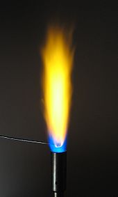
A flame test for sodium. Note that the yellow color in this gas flame does not arise from the blackbody emission of sootparticles (as the flame is clearly a blue premixed complete combustion flame) but instead comes from the spectral lineemission of sodium atoms, specifically the very intense sodium D lines.
When looking at a flame's temperature there are many factors which can change or apply. One important one is that a flame's color does not necessarily determine a temperature comparison because black-body radiation is not the only thing that produces or determines the color seen; therefore it is only an estimation of temperature. Here are other factors that determine its temperature:
Adiabatic flame; i.e., no loss of heat to the atmosphere (may differ in certain parts).
Atmospheric pressure
Percentage oxygen content of the atmosphere.
The fuel being burned (i.e., depends on how quickly the process occurs; how violent the combustion is.)
Any oxidation of the fuel.
Temperature of atmosphere links to adiabatic flame temperature (i.e., heat will transfer to a cooler atmosphere more quickly).
How stoichiometric the combustion process is (a 1:1 stoichiometricity) assuming no dissociation will have the highest flame temperature... excess air/oxygen will lower it and likewise not enough air/oxygen.
In fires (particularly house fires), the cooler flames are often red and produce the most smoke. Here the red color compared to typical yellow color of the flames suggests that the temperature is lower. This is because there is a lack of oxygen in the room and therefore there isincomplete combustion and the flame temperature is low, often just 600–850 °C (1,112–1,562 °F). This means that a lot of carbon monoxide is formed (which is a flammable gas if hot enough) which is when in Fire and Arson investigation there is greatest risk of backdraft. When this occurs flames get oxygen, carbon monoxide combusts and temporary temperatures of up to 2,000 °C (3,632 °F) occur.
Flame temperatures of common items include a candle at 1,400 °C (2,600 °F), a blow torch – at around 1,600 °C (2,900 °F) a propane torch at 1,995 °C (3,620 °F), or a much hotteroxyacetylene combustion at 3,000 °C (5,400 °F).

Common flame temperatures

This section may contain original research. Please improve it by verifying the claims made and adding references. Statements consisting only of original research may be removed. More details may be available on the talk page. (September 2009)
This is a rough guide to flame temperatures for various common substances (in 20 °C air at 1 atm. pressure):
Material burned
Flame temperature (°C)
Charcoal fire
750–1,200
Methane (natural gas)
900–1,500 
Propane blowtorch
1,200–1,700
Candle flame
~1,100 (majority), hot spots may be 1300–1400
Magnesium
1,900–2,300
Hydrogen torch
Up to ~2,000
Acetylene blowlamp/blowtorch
Up to ~2,300 
Oxyacetylene
Up to ~3,300 
Backdraft flame peak
1,700–1,950
Bunsen burner flame
900–1,600 (depending on the air valve)
Material burned
Max. flame temperature (°C, in air, diffusion flame)
Wood
1027
Gasoline 1026
Methanol 1200
Kerosene 990
Animal fat 800–900
Charcoal (forced draft) 1390
Hottest flame temperature
Cyanogen produces a very hot flame with a temperature of over 4,525 °C (8,180 °F) when it burns in oxygen. Dicyanoacetylene, a compound of carbon and nitrogen with chemical formula C4N2 burns in oxygen with a bright blue-white flame at a temperature of 5260 K (4990 °C, 9010 °F), and at up to 6000 K in ozone. This high flame temperature is also the result of the absence of hydrogen, and, therefore, water as a combustion product. Because of its high specific heat, water vapor as a combustion product tends to lower the flame temperature of hydrogen containing compounds. The endothermic dissociation of water at high temperatures above 2000 °C also prevents flame temperatures to rise above 3000 to 4000 °C.
 Cool flames
Main article: Cool flame
At temperatures as low as 120 °C, fuel-air mixtures can react chemically and produce very weak flames called cool flames. The phenomenon was discovered by Humphry Davy in 1817. The process depends on a fine balance of temperature and concentration of the reacting mixture, and if conditions are right it can initiate without any external ignition source. Cyclical variations in the balance of chemicals, particularly of intermediate products in the reaction, give oscillations in the flame, with a typical temperature variation of about 100 K, or between "cool" and full ignition. Sometimes the variation can lead to explosion.

Flames in microgravity
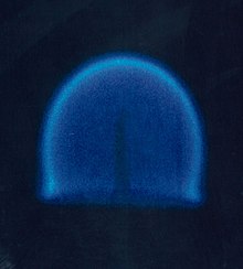
In zero gravity, convection does not carry the hot combustion products away from the fuel source, resulting in a spherical flame front.


In 2000, experiments by NASA confirmed that gravity plays an indirect role in flame formation and composition. The common distribution of a flame under normal gravity conditions depends on convection, as soot tends to rise to the top of a flame (such as in a candle in normal gravity conditions), making it yellow. In microgravity or zero gravity environment, such as in orbit, natural convection no longer occurs and the flame becomes spherical, with a tendency to become bluer and more efficient. There are several possible explanations for this difference, of which the most likely is the hypothesis that the temperature is sufficiently evenly distributed that soot is not formed and complete combustion occurs.Experiments by NASA reveal thatdiffusion flames in microgravity allow more soot to be completely oxidized after they are produced than do diffusion flames on Earth, because of a series of mechanisms that behave differently in microgravity when compared to normal gravity conditions.These discoveries have potential applications in applied science and industry, especially concerning fuel efficiency.

Photocell


A photocell, also known as a photoresistor, is a device that changes its electrical conductivity when light shines on it. In the picture, the electricity flows through the reddish part. Normally, when light shines on it, then more electricity flows through. When it is dark, almost no electricity flows through. Selenium can be used to make photocells, although some other chemicals can be used.


Semiconductors are used to make photocells. When the light shines into the photocell, it "loosen"s the electrons, allowing them to flow and make an electrical current.

Burner

Gas burner or oil burner, a mechanical device that burns a gas or liquid fuel into a flame in a controlled manner

Gas burner..........................
A gas burner is a device to generate a flame to heat up products using a gaseous fuel such as acetylene, natural gas or propane. Some burners have an air inlet to mix the fuel gas with air to make a complete combustion. Acetylene is commonly used in combination with oxygen.


It has many applications such as soldering, brazing and welding, the latter using oxygeninstead of air for getting a hotter flame which is required for melting steel. For laboratory uses a natural gas fired Bunsen burner is used. For melting metals with melting points of up to 1100 °C such as copper, silver and gold a propane burner with natural drag of air can be used.


Oil Burner.........................

An oil burner is a heating device which burns fuel oil. The oil is atomized in to a fine spray usually by forcing it under pressure through a nozzle. This spray is usually ignited by an electric spark with the air being forced through by an electric fan.

Fuel injection


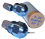
Used nozzles from an oil burner
Fuel is injected into the combustion chamber by a spray nozzle.
The nozzles are usually supplied with high pressure oil. Because of problems with erosion, and blockage due to lumps in the oil, they need frequent replacement typically every year. Fuel nozzles are usually rated in fuel volume flow per unit time e.g. USGal/h (U.S. Gallons per hour).
A fuel nozzle is characterized by 3 features:
  • A flow of 7 bar pump pressure (0.65 (USGal / h))
  • The spray characteristic (S)
  • The spray angle (60 °)
Alternatively fuel may be passed over a tiny orifice fed with compressed air. This arrangement is referred to as babington atomiser/nozzle after its inventor. As the oil flows over the nozzle , the fuel needn't be under any great pressure. If the pump can handle such the oil may even contain lumps such as scraps of food. Because it is only compressed air that passes through the orifice hole, such nozzles do not suffer much from erosion.


Oil pump
A fuel oil pump consists of two parts:
  • Gear pump type
This sucks the oil and increases the pressure in the nozzles to 15 bar maximum. Usually a gear pump of the sickle type is used. This type of pump is a simple and therefore cheap pumpconsisting of one or more radical pairs of gears and with a very small space between the gears and the pump casing. Gear pumps are used frequently in oil burners because of their simplicity, stability and low price.
  • Pressure regulator
To set the heat output of the burner, the rate of fuel delivery via the nozzle must be adjustable. This is often achieved by an adjustable pressure relief valve between the pump and the nozzle. When the set pressure is reaches usually 10 - 11 bar, this valve opens and allows excess oil through a bypass back to the fuel tank or pump suction.


Electromagnetic valve


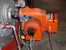
A small two-stage industrial burner. The blue cubes are the coils of the two electromagnetic magnetic.
This enables fuel to be shut off from the sprayer by electrical control. This helps avoid drips when it is inactivated. It also eases the purging of the burner (and any boiler) of fuel mist, during start up, or while restarting after a misfire. If the burner were not purged the oil/air mixture could explode dangerously.

Fan

The fan blows air into the combustion chamber. The rotor of the fan is powered by aelectric motor.


Ignitors

Some oil burners use glow bars which operate much like the glow plugs of a diesel engine
Many use high voltage generated by a voltage-step up transformer and use a spark plug to initiate ignition


Photocell


LDR
A light sensitive resistor (LDR) detects the flame. The LDR (or Light Dependent Resistor) resistor is an electrical resistor whose value changes by the amount of light that it present. The resistance value of an LDR becomes smaller, as the LDR is more and more exposed. The material is usually cadmium sulfide, the dark resistance is 1.10 MΩ resistor while the light resistance is about 75-300 Ω. LDR's have a relatively slow response time.


Capacitor start motor


Schematic of a capacitor start motor.
The fan and motor which drives the oil pump is usually a capacitor start motor. It is a vortex shortage tank motor because it also contains a short cage or cage[disambiguation needed ] holds. The difference with a three-phase motor is in the stator. Where the vortex power motor has three coils aligned at 120° in the stator, the capacitor start motor holds one main winding and one auxiliary winding aligned at 90°. The phase shift of 90° between the main winding and the auxiliary winding is achieved by a connected capacitor which feeds the auxiliary winding and is connected on the single-phase AC mains. The capacitor will achieve a phase shift of 90° between the main and the auxiliary winding, producing an acceptable initial torque. This motor is intended for continuous operation.