COMPRESSOR

Kaeser Compressors, Inc. offers a complete line of air system products including rotary screw compressors with the highly efficient Sigma Profile and the Sigma Control system, Mobilair portable compressors, Omega rotary lobe blowers, vacuum packages, refrigerated and desiccant dryers, filters, condensate management systems and a variety of related products.

Download and Read PDF files


1 Airend

2 Energy-saving electric    motor

3 Motor grease nipples

4 Inlet valve

5 Minimum pressure/check valve

6 Combined Auxiliary Vent Valve

7 Fluid cooler with mounted thermostatic valve and fluid-micro filter

8 Compressed air after cooler

9 Two-stage air inlet filter

10 Fluid separator tank with separator cartridge
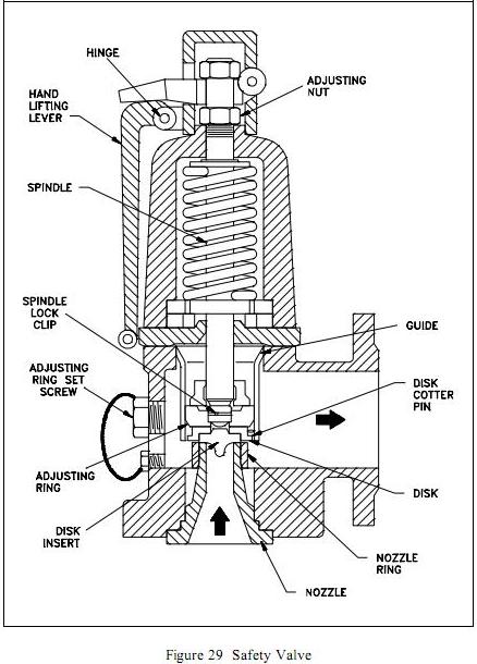
11 Safety Valve

12 Anti Vibration Dampers

13 Sigma Control


Quick Details
Place of Origin: Austria Brand Name: Kaeser Model Number: ESD 351
Type: Screw

Configuration: Stationary
Lubrication Style: Lubricated
Condition: Used Motor: 200 kW

Max Bar: 8.50
FAD: 36.80 m3/min

Color: Yellow


The atmospheric air drawn into a compressor is a mixture of gases that always contains water vapour. However, the amount of water vapour that air can carry varies and is mostly dependent on temperature. As air temperature rises – which occurs during compression – the air's capability to hold moisture increases also. When the air is cooled its capacity to hold moisture reduces, which causes the water vapour to condense. This condensate is then removed in the centrifugal separator, or the air receiver, downstream from the compressor. Even then, the air can still be completely saturated with water vapour. This is why, as the air cools further, significant amounts of condensate can accumulate in the air distribution piping and at take-off points. System failure, production downtime and costly service and repair work are therefore unavoidable without additional air drying.


On average, a compressor sucks in up to 190 million particles of dirt, hydrocarbons, viruses and bacteria with every cubic meter of atmospheric air. The compressor itself can only remove the larger dirt particles and the majority of the contaminants remain in the compressed air. This means that for most applications careful treatment of the air is necessary: Clean, quality compressed air maximises air-tool service life, ensures that pneumatic machinery and control systems operate at the peak of their performance and keeps pipes & valves free from contaminants. It therefore not only reduces service, maintenance and repair costs, but can also reduce initial investment costs.

Condensate treatment technology  


ECO -DRAIN
ECO DRAIN condensate drains ensure safe, reliable condensate drainage without air loss, even under conditions with widely fluctuating accumulation and high particle / oil content.
Condensate treatment system AQUAMAT
The AQUAMAT system enables the compressor user to carry out in-house condensate treatment and thereby greatly reduce the overall cost of condensate waste treatment and disposal. Condensate treatment with the KAESER AQUAMAT system saves up to 90% of the disposal costs that would be required for a specialist company to dispose of the condensate.

     Centrifugal Separator
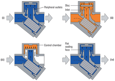
FUNCTION
The centrifugal separator removes large volumes of condensate from the compressed air. Optimised design enhances the centrifuge effect and ensures a near constant degree of condensate separation over a wide flow volume range. Furthermore, particles up to 5 μm are also "washed out".


Application:
A centrifugal separator is recommended for systems where the refrigeration dryer is installed “directly” downstream from the rotary screw compressor.
The centrifugal separator is installed between the compressor and the refrigeration dryer and removes the ‘liquid condensate’ from the compressed air. This provides the refrigeration dryer with additional reserve drying capacity. This is particularly important at high ambient temperatures in order to ensure that the required pressure dew point is consistently maintained.
KAESER centrifugal separators are maintenance-free.


Tip:

Each centrifugal separator should be fitted with an electronic ECO Drain condensate drain (available as a complete set with all necessary components).

   Air Receivers
KAESER = Quality
Whether 90 or 10,000 litres, all KAESER compressed air receivers are designed and manufactured to the highest quality standards to ensure exceptional durability. You only get genuine KAESER quality with genuine KAESER air receivers. The same care and attention given to providing KAESER air receivers with outstanding corrosion resistance and perfect sealing (thanks to the precision thread finishing process that takes place after galvanisation) is also given to transportation. Plastic protective caps are fitted to all connection flanges on the air receiver to ensure that each unit reaches the customer in perfect condition.


SAFETY VALVES


INTRODUCTION


A safety valve is a valve mechanism for the automatic release of a substance from a boiler, pressure vessel, or other system when the pressure or temperature exceeds preset limits.

It is part of a bigger set of pressure safety valves (PSV) or pressure relief valves (PRV). The other parts of the set are relief valves, safety relief valves, pilot-operated relief valves, low pressure safety valves, and vacuum pressure safety valves.

Safety valves were first used on steam boilers during the industrial revolution. Early boilers without them were prone to accidental explosion.

Vacuum safety valves (or combined pressure/vacuum safety valves) are used to prevent a tank from collapsing while emptying it or when cold rinse water is used after hot CIP or SIP. The calculation method is not defined in any norm when sizing a vacuum safety valve, particularly in the hot CIP / cold water scenario, but some manufacturers  have developed simulations to do so.

Function and design


The earliest and simplest safety valve on the steam digester in 1679 used a weight to hold the steam pressure (this design is still commonly used on pressure cookers); however, these were easily tampered with or accidentally released. On the Stockton and Darlington Railway, the safety valve tended to go off when the engine hit a bump in the track. A valve less sensitive to sudden accelerations used a spring to contain the steam pressure, but these (based on a Salter spring balance) could still be screwed down to increase the pressure beyond design limits. This dangerous practice was sometimes used to marginally increase the performance of a steam engine. In 1856 John Ramsbottom invented a tamper-proof spring safety valve that became universal on railways.

Safety valves also evolved to protect equipment such as pressure vessels (fired or not) and heat exchangers. The term safety valve should be limited to compressible fluid application (gas, vapor, or steam).

The two general types of protection encountered in industry are thermal protection and flow protection.

For liquid-packed vessels, thermal relief valves are generally characterized by the relatively small size of the valve necessary to provide protection from excess pressure caused by thermal expansion. In this case a small valve is adequate because most liquids are nearly incompressible, and so a relatively small amount of fluid discharged through the relief valve will produce a substantial reduction in pressure.

Flow protection is characterized by safety valves that are considerably larger than those mounted in thermal protection. They are generally sized for use in situations where significant quantities of gas or high volumes of liquid must be quickly discharged in order to protect the integrity of the vessel or pipeline. This protection can alternatively be achieved by installing a high integrity pressure protection system (HIPPS).

For more info...

IMPORTANCE:..
Safety Valves are the most important fittings on the boiler.  They should open to release pressure when pressure inside the boiler exceeds the maximum allowable working pressure or MAWP.  Safety valves are installed at the highest part of the steam side of the boiler.  No other valve shall be installed between the boiler and the safety valve.  Safety valve capacity is measured for steam that can be discharged per hour.  The safety valve will remain open until sufficient steam is released and there is a specific amount of drop in pressure.  This drop in pressure is the blow-down of the safety valve.  Safety valve capacity and blow-down is listed on the data plate on the safety valve.  Spring-loaded safety valves are the most common safety valves.  A spring exerts pressure on the valve against the valve seat to keep the valve closed.  When pressure inside the boiler exceeds the set popping pressure, the pressure forces the valve open to release.   The ASME Code specifies the design, materials and construction of safety valves.   The number of safety valves required and the frequency and procedures for testing safety valves is also specified by the ASME Code.  Adjustment or repairs to safety valves must be performed by the manufacturer or an assembler authorized by the manufacturer.
Water fittings and accessories control the amount, pressure and temperature of water supplied to and from the boiler.  Water in the boiler must be maintained at the normal operating water level.  Low water conditions can damage the boiler and could cause a boiler explosion. High water conditions can cause carryover.  Carryover occurs when small water droplets are carried in steam lines.  Carryover can result in water hammer.  Water hammer is a banging condition caused by hydraulic pressure that can damage equipment.


STEAM TRAPS

A steam trap is an automatic valve designed to remove condensate, air, and CO2 from the steam system. The trap opens automatically to discharge condensate and closes to prevent steam loss from the system.
 Over the years, a number of types of steam traps have been marketed. Although they vary in design, they all use one or more of the three basic operating principles relating to density, temperature, or velocity. Four types of steam traps have emerged which presently fill most industrial and process requirements.


STEAM TRAPS...........................          (READ & DOWNLOAD)


There are three basic types of steam trap into which all variations fall


1.    Thermostatic (operated by changes in fluid temperature).
                           The temperature of saturated steam is determined by its pressure. In the steam space, steam gives up its enthalpy of evaporation (heat), producing condensate at steam temperature. As a result of any further heat loss, the temperature of the condensate will fall. A thermostatic trap will pass condensate when this lower temperature is sensed. As steam reaches the trap, the temperature increases and the trap closes.


 2.     Mechanical (operated by changes in fluid density).
                      This range of steam traps operates by sensing the difference in density between steam and condensate. These steam traps include 'ball float traps' and 'inverted bucket traps'. In the 'ball float trap', the ball rises in the presence of condensate, opening a valve, which passes the denser condensate. With the 'inverted bucket trap', the inverted bucket floats when steam reaches the trap and rises to shut the valve. Both are essentially 'mechanical' in their method of operation.
•   


  3.   Thermodynamic (operated by changes in fluid dynamics).
                   Thermodynamic steam traps rely partly on the formation of flash steam from condensate. This group includes 'thermodynamic', 'disc', 'impulse' and 'labyrinth' steam traps.


Mechanical (operated by changes in fluid density).


Inverted Bucket Steam Traps


                      OUT SIDE VIEW                                                        INSIDE VIEW

Inverted bucket steam traps are the most robust type of mechanical trap and resist water hammer.  The design works on the principle of differentiating between the density of steam and water condensate.  Steam entering under the submerged, inverted bucket causes it to float, which closes the discharge valve located at the top of the trap.   Condensate entering the trap causes the bucket to sink, opening the valve to remove condensate.  Normally there is a small vent in the top of the bucket, which allows non-condensable gases to pass through for discharge with the condensate.  Inverted bucket steam traps are often found on higher-pressure steam systems, but they have also found use in lower-pressure service, where one might normally find float and thermostatic traps, because of their low maintenance and long lasting characteristics.  With the addition of a check valve at the trap inlet, the inverted bucket can also be used to remove condensate from superheated steam lines.  They must be installed in a vertical position and are used for a wide variety of service applications.

Ball Floating Steam Trap


 Float  traps are mechanical units that operate on both density and temperature principles. The float valve operates on the density principle. A level connects the ball float to the valve and seat. Once condensate reaches a certain level in the trap, the float rises, opening the orifice and draining condensate. A water seal formed by the condensate prevents live steam loss

Since the discharge valve is under water, it is not capable of venting air and non-condensables. When the accumulation of air and con-condensable gases causes a significant temperature drop, a thermostatic air vent in the top of the trap discharges them. The thermostatic vent opens at a temperature a few degrees below saturation, so it's able to handle a large volume of air-through an entirely separate orifice-but at a slightly reduced temperature.


Thermostatic Steam Traps


Thermostatic steam traps open and close with the movement of a temperature sensitive element.  As steam condenses, the newly formed condensate is at steam temperature, but as it flows to the steam trap, it cools.  When the temperature inside  the steam trap has dropped to a specified value below the steam temperature, the thermostatic valve will open, and line pressure will force condensate and noncondensable gases out of the trap.  Once entering steam reheats the trap to the desired temperature, the thermostatic valve will close preventing the discharge of live steam. 

There are two basic designs for a thermostatic steam trap, a bimetallic and a balanced pressure design.  Both use the difference in temperature between live steam and condensate or air to control the release of water and noncondensable gases from the steam line.


Bimetallic Thermostatic Steam Trap


One type of thermostatic steam trap uses bimetallic elements to accuate a ball (left) or needle (right) valve assembly that discharges condensate and noncondensable gases.  
The ball valve design uses a multi-segment bimetallic element to actuate a free-floating ball valve on the downstream side of the trap.  The element deflects against the line pressure with a variable increasing force in relation to rising steam pressure and temperature.  The force exerted by the bimetallic element against line pressure closely parallels the steam curve, which permits the trap to operate throughout a wide pressure range without adjustment.  The heart of this design is the bimetallic elements that consists of two dissimilar metals bonded together to form a composite strip.   Due to the differing coefficients of expansion of the two metals, the strip will bend or deflect when subjected to a change in temperature.
Most designs have the ball valve wide open when the trap is cold.  This allows air and condensate to discharge rapidly during initial pressurization of the steam line.  As warmer condensate enters the trap, the bimetallic element deflects slowly to close the valve.   By the time live steam reaches the trap, the element has deflected so as to completly close the ball valve on the exit side of the trap.
When condensate or air enters the trap, their temperature is below that of saturated steam and the consequent reaction of the element is insufficient to keep the valve tightly closed allowing  line pressure on the valve to overcome the pull of the element and open the valve.  When live steam again enters the trap, the element deflects to once again tightly close the exit side ball valve preventing the loss of live steam.


Balanced Pressure Thermostatic Steam Trap

Balanced pressure thermostatic steam traps open and close via the expansion and contraction of a temperature sensitive element that responds to the lower temperatures created by condensate and noncondensable gases in the trap.  The operating unit within the trap, a pressure-balanced disc or bellows, is filled with a liquid having a saturation temperature slightly below that of water.  With rising temperatures in the trap, the liquid contained in the active element evaporates.  The resulting internal pressure causes the bellows or disc to expand and close the valve.  As condensate or air enter the trap, the temperature within the trap decreases allowing some of the liquid in the bellows to condense, which reduces the pressure inside the bellows.  This reduction in pressure causes the bellows to contract. and open the valve.


Thermodynamic or Disk Steam Traps

The thermodynamic trap is an extremely robust steam trap with a simple mode of operation. The trap operates by means of the dynamic effect of flash steam as it passes through the trap, as depicted in Figure 4.i. The only moving part is the disc above the flat face inside the control chamber or cap. On start-up, incoming pressure raises the disc, and cool condensate plus air is immediately discharged from the inner ring, under the disc, and out through three peripheral outlets (only 2 shown, Figure 4. ii).Hot condensate flowing through the inlet passage into the chamber under the disc drops in pressure and releases flash steam moving at high velocity. This high velocity creates a low pressure area under the disc, drawing it towards its seat (Figure 4.iii).At the same time, the flash steam pressure builds up inside the chamber above the disc, forcing it down against the incoming condensate until it seats on the inner and outer rings. At this point, the flash steam is trapped in the upper chamber, and the pressure above the disc equals the pressure being applied to the underside of the disc from the inner ring. However, the top of the disc is subject to a greater force than the underside, as it has a greater surface area.Eventually the trapped pressure in the upper chamber falls as the flash steam condenses. The disc is raised by the now higher condensate pressure and the cycle repeats (Figure 4. iv).

Thermodynamic steam traps are preferably installed with the controlling disc in a horizontal position.  The traps are used in applications where there will be no adverse effects from a temporary accumulation of condensate due to the intermittent operation of the trap.  These applications include: pressing units, drying units, and steam jacket pipelines.

Fire Tube Boiler

(Saturated steam)

A fire-tube boiler is a type of boiler in which hot gases from a fire pass through one or more tubes running through a sealed container of water. The heat of the gases is transferred through the walls of the tubes by thermal conduction, heating the water and ultimately creating steam.

Firetube boilers are often characterized by their number of passes, referring to the number of times the combustion (or flue) gases flow the length of the pressure vessel as they transfer heat to the water. Each pass sends the flue gases through the tubes in the opposite direction. To make another pass, the gases turn 180 degrees and pass back through the shell. The turnaround zones can be either dryback or water-back. In dryback designs, the turnaround area is refractory lined. In water-back designs, this turnaround zone is water-cooled, eliminating the need for the refractory lining.


The number of passes the boiler contains affects the boiler efficiency, and its first cost to manufacturer. The more heat transfer surfaces the boiler has, the more efficient it can be. However, this also increases the amount of material it contains and therefore the first cost.

Identify the number of passes that the boiler has be which end the flue is on, and the approximate size of the vessel.


Water Tube Boiler

(Superheated steam)

A water tube boiler is a type of boiler in which water circulates in tubes heated externally by the fire. Water tube boilers are used for high-pressure boilers. Fuel is burned inside the furnace, creating hot gas which heats water in the steam-generating tubes. ...
The water-tube boiler was patented in 1867 by American inventors George Herman Babcock and Stephen Wilcox. In the water-tube boiler, water flowed through tubes heated externally by combustion gases, and steam was collected above in a drum. Water tube boilers are very huge and their water holding capacity is enormous. The water-tube boiler became the standard for all large boilers as they allowed for higher pressures than earlier boilers, higher than 30 bar. Example, Babcock & Wilcox boiler manufactured at Thermax Boilers Ltd., Pune.

It is a horizontal, externally fired, stationary, high pressure, water tube boiler with a super heater as shown below.


The coal is fed from hopper on to the grate where it is burnt. The flue gases are deflected by the fire brick baffles so that they pass across the left side of the tubes in a beneficial path transferring heat to water in the tubes and to the steam in the super heater and finally they escape into the atmosphere through the chimney. The drought is regulated by a damper placed at the back chamber.


The position of water tubes near the furnace is heated to a higher temper than the rest. Owing to higher temperature, the density of water decreases and hence the water rises through the uptake header and short tube to the drum. The water at the back end, which is at a lesser temperature now travels down through the long tube and the downtake header. Thus, a continuous circulation of water called as natural circulation is established between the water tubes and the drum. The steam produced gets collected above the water in the drum.Here, saturated steam is drawn off the top of the drum.


Since water droplets can severely damage turbine blades, dry steam from the steamdrum is again heated to generate superheated steam at 730°F (390°C) or higher in order to ensure that there is no water entrained in the steam. Cool water at the bottom of the steam drum returns to the feedwater drum via large-bore 'downcomer tubes', where it helps pre-heat the feedwater supply. To increase the economy of the boiler, the exhaust gasses are also used to pre-heat the air blown into the furnace and warm the feedwater supply. Such water-tube boilers in thermal power station are also called steam generating units.


THE BOILER HOUSE

Introduction:...
ARL has vast range of operation therefore it needs versatility of process. This flexibility can’t be achieved without utilities operations. Utilities are the backbone of any process industry and in these utilities operations steam generation got the key importance. Steam is generated for variety of purposes. In case of refinery, steam is used mainly for stripping purpose. Other facilities of utilities operations here in ARL are instrument air, service air, plant water, soft water, drinking water, raw water, firewater, cooling water, fuel oil for plants and caustic soda plant facility. 


A boiler is a closed vessel in which water under pressure is transformed into steam by the application of heat. In the boiler furnace, the chemical energy in the fuel is converted into heat, and it is the function of the boiler to transfer this heat to the contained water in the most efficient manner. The boiler should also be designed to generate high quality steam for plant use. A flow diagram for a  boiler house plant is presented.
Types
Two principal types of boilers are used for industrial applications:

Boiler Related Parts..................................