Gas burner or oil burner, a mechanical device that burns a gas or liquid fuel into a flame in a controlled manner
Gas burner..........................
A gas burner is a device to generate a flame to heat up products using a gaseous fuel such as acetylene, natural gas or propane. Some burners have an air inlet to mix the fuel gas with air to make a complete combustion. Acetylene is commonly used in combination with oxygen.
It has many applications such as soldering, brazing and welding, the latter using oxygeninstead of air for getting a hotter flame which is required for melting steel. For laboratory uses a natural gas fired Bunsen burner is used. For melting metals with melting points of up to 1100 °C such as copper, silver and gold a propane burner with natural drag of air can be used.


Oil Burner.........................
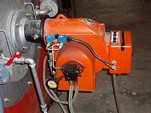
An oil burner is a heating device which burns fuel oil. The oil is atomized in to a fine spray usually by forcing it under pressure through a nozzle. This spray is usually ignited by an electric spark with the air being forced through by an electric fan.
A gas burner is a device to generate a flame to heat up products using a gaseous fuel such as acetylene, natural gas or propane. Some burners have an air inlet to mix the fuel gas with air to make a complete combustion. Acetylene is commonly used in combination with oxygen.
It has many applications such as soldering, brazing and welding, the latter using oxygeninstead of air for getting a hotter flame which is required for melting steel. For laboratory uses a natural gas fired Bunsen burner is used. For melting metals with melting points of up to 1100 °C such as copper, silver and gold a propane burner with natural drag of air can be used.


Oil Burner.........................
An oil burner is a heating device which burns fuel oil. The oil is atomized in to a fine spray usually by forcing it under pressure through a nozzle. This spray is usually ignited by an electric spark with the air being forced through by an electric fan.
Fuel injection
Fuel is injected into the combustion chamber by a spray nozzle.
The nozzles are usually supplied with high pressure oil. Because of problems with erosion, and blockage due to lumps in the oil, they need frequent replacement typically every year. Fuel nozzles are usually rated in fuel volume flow per unit time e.g. USGal/h (U.S. Gallons per hour).
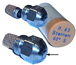
A fuel nozzle is characterized by 3 features:
- A flow of 7 bar pump pressure (0.65 (USGal / h))
- The spray characteristic (S)
- The spray angle (60 °)
Alternatively fuel may be passed over a tiny orifice fed with compressed air. This arrangement is referred to as babington atomiser/nozzle after its inventor. As the oil flows over the nozzle , the fuel needn't be under any great pressure. If the pump can handle such the oil may even contain lumps such as scraps of food. Because it is only compressed air that passes through the orifice hole, such nozzles do not suffer much from erosion.
A fuel oil pump consists of two parts:
- Gear pump type
This sucks the oil and increases the pressure in the nozzles to 15 bar maximum. Usually a gear pump of the sickle type is used. This type of pump is a simple and therefore cheap pumpconsisting of one or more radical pairs of gears and with a very small space between the gears and the pump casing. Gear pumps are used frequently in oil burners because of their simplicity, stability and low price.
- Pressure regulator
To set the heat output of the burner, the rate of fuel delivery via the nozzle must be adjustable. This is often achieved by an adjustable pressure relief valve between the pump and the nozzle. When the set pressure is reaches usually 10 - 11 bar, this valve opens and allows excess oil through a bypass back to the fuel tank or pump suction.
Electromagnetic valve
This enables fuel to be shut off from the sprayer by electrical control. This helps avoid drips when it is inactivated. It also eases the purging of the burner (and any boiler) of fuel mist, during start up, or while restarting after a misfire. If the burner were not purged the oil/air mixture could explode dangerously.
Fan
The fan blows air into the combustion chamber. The rotor of the fan is powered by aelectric motor.
Ignitors
Some oil burners use glow bars which operate much like the glow plugs of a diesel engine
Many use high voltage generated by a voltage-step up transformer and use a spark plug to initiate ignition
Photocell
A light sensitive resistor (LDR) detects the flame. The LDR (or Light Dependent Resistor) resistor is an electrical resistor whose value changes by the amount of light that it present. The resistance value of an LDR becomes smaller, as the LDR is more and more exposed. The material is usually cadmium sulfide, the dark resistance is 1.10 MΩ resistor while the light resistance is about 75-300 Ω. LDR's have a relatively slow response time.
Capacitor start motor
The fan and motor which drives the oil pump is usually a capacitor start motor. It is a vortex shortage tank motor because it also contains a short cage or cage[disambiguation needed  ] holds. The difference with a three-phase motor is in the stator. Where the vortex power motor has three coils aligned at 120° in the stator, the capacitor start motor holds one main winding and one auxiliary winding aligned at 90°. The phase shift of 90° between the main winding and the auxiliary winding is achieved by a connected capacitor which feeds the auxiliary winding and is connected on the single-phase AC mains. The capacitor will achieve a phase shift of 90° between the main and the auxiliary winding, producing an acceptable initial torque. This motor is intended for continuous operation.


0 comments:
Post a Comment